

|
User Guide |
| User Guide | Transform Guide | OSW on the Web | |
This chapter describes the use of OSW programs to define and manipulate audio signals. Using OSW, you can synthesize musical sounds, process audio input, route signals to audio outputs or convert it into other data types. This chapter describes how OSW treats signals and some of the functions you can use to manipulate them.
A sound is commonly modeled as a waveform signal, that is a function y(t) representing the amplitude of the sound at time t:

In digital systems, the continuous time variable t is replaced by a discrete variable n. The resulting digital waveform y(n/S) represents the amplitude sampled at time n/S where S is the sampling rate. However, it is common practice to assume the relationship between sample index n, time t, and sampling rate S and refer to the digital waveform as y(n) [Chaudhary 2001].
Most OSW transforms that manipulate audio signals have inlets and/or outlets of type Samples. "Samples" is an OSW data type that represents digitally sampled signals as vectors of 32-bit floating-point numbers. You can recognize the presence of the Samples data type by red inlets, outlets and wires.
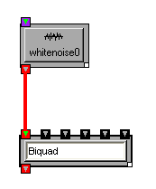
For those rare instances where one absolutely must have an integer representation of signals, there are additional data types IntegerSamples, Integer16Samples and ByteSamples for 32-bit, 16-bit and 8-bit integers, respectively.
The audio-signal data types are nothing to be particularly afraid of. They work like any other data type in OSW. You can connect outlets of type Samples to inlets of type Samples. You can also print them, and even store them in Lists or Blobs.
OSW automatically determines the sample rate for a particular signal based on the input and/or output devices to which it is connected. Most of the time, this is 44.1kHz, sometimes 48kHz. Signals are usually transmitted in blocks (otherwise known as vectors) of 64 samples. Both the sampling rate and block size can be dynamically adjusted by the user via the Audio Devices dialog box (under the Options menu). The format of the samples are always 32-bit floating-point numbers (unless you use a signal type other than Samples). OSW automatically converts between floating-point and the native format of your audio devices.
Because OSW dynamically determines sample rates and block sizes and converts between its floating-point Samples and the native sample format, you will probably not have to worry about these issues in your patches. Most signal-processing transforms are written to automatically adjust for changes in sampling rate or block size. You can test this out with the help patch for the Sinewave transform. Adjust the sample rate using the Options/Audio Devices menu option and notice that the frequency of the sine wave remains the same.
On issue that programmers should be aware of, however, is that floating-point values greater than 1 or less than -1 are clipped, so you should try to keep your signals between 1 and -1, at least when they reach an AudioOutput transform. Other than output clipping, users are free to use the entire dynamic range available.
If you have made it this far through the documentation, you have likely already encounted the AudioOutput transform. This is one of the most important transforms in OSW, and the only way to get signals from OSW patches out to your audio hardware.
For standard stereo or mono output, you can simply click on the instance of AudioOutput available in the docked transform toolbar and drag it onto your patch.
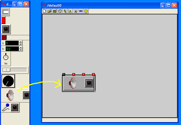
The AudioOutput transform has a button on it to turn it on or off. Turning on an AudioOutput transform opens your audio hardware for output and starts sending signals. You can also connect an Integer or a Boolean (e.g., the output of a Toggle transform) to the left-most inlet of the AudioOutput to turn it on or off from somewhere else in your patch.
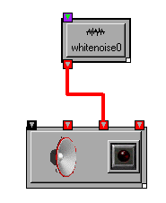
Now lets make some noise, literally! Create a WhiteNoise transform and connect it to the right-most inlet of your AudioOutput transform.
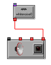
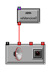
If the AudioOutput is on, you should start hearing the noise immediately, if not, turn it on to hear the noise. Assuming you have stereo speakers, you should be hearing the noise from both speakers. The right-most inlet of AudioOutput, called mix, always sends the signal to all channels associated with the output transform. To send a signal to each of the channels individually, use the remaining inlets between the on/off inlet on the left and the mix on the right. You can try it right now by disconnecting the WhiteNoise transform (select the wire and press Delete) and connecting it first to the left channel (second inlet) and then to the right channel (third inlet). You should first hear noise from your left speaker and then from your right speaker (if not, there is probably something wrong with your speaker wires).
|
|
Stereo is fine for many applications (even mono is good enough sometimes), but many modern soundcards can support more channels of audio. It is not uncommon to see four or eight channels in pro-music hardware, and 5.1 or 6.1 surround-sound is becoming more common in the consumer market.
OSW allows you to take advantage of additional channels supported by your audio hardware. Instead of using the default AudioOutput transform provided on the toolbar, type "AudioOutput" followed by the numbers of the channels you want to support. For example, to support four channels, type: "AudioOutput 1 2 3 4"

Assuming channels 1 through 4 are indeed available, you will be presented with an AudioOutput transform with extra inlets for the additional channels.
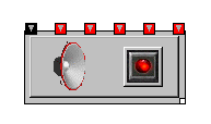
Similar to the stereo example, the left inlet is used for remote switching of the audio output and the far right inlet is used to mix all the channels (in this case, all four channels). The channels selected for an AudioOutput transform need not be contiguous or in any order. For example, if your audio hardware supports eight channels, you could create an AudioOutput transform that accesses only the even-numbered channels.

If you have more than one audio device (e.g., two or more soundcards), the channel numbers are continued across devices so that you can use them all from OSW. For example, if you have both a stereo soundcard and a soundcard with four channels, channels 1 and 2 might correspond to the first card and channels 3 through 6 to the second. You can learn more about the audio devices in your system, including channel assignments, by selecting the "Audio Devices" menu item under Preferences.
OSW supports incoming audio via the AudioInput transform. This transform is also available on the toolbar and easily recognizable by its microphone icon:

AudioInput works similar to AudioOutput, including default support for stereo sources and optional support for multiple channels (should you be lucky enough to own audio hardware with multiple inputs) via channel specifications. Also similar to AudioInput, it has a button to turn the signal on and off and an optional inlet to control its state from elsewhere in your patch. Of course, the channel ports are outlets instead of inlets, and there is no notion of a "mix" channel for audio input.
OSW includes many ways to generate signals. You have already encountered two: Sinewave and WhiteNoise. Both of these transforms fall into a general class called oscillators that generate synthetic waveforms based on various mathematical functions. Additional oscillator transforms in OSW include:
From these transforms, you can generate even more oscillators such as pulse trains. Explore the help and tutorial patches referenced in this section to get a feel for the some of the basic sounds you can make. Keep in mind these are only building blocks, you can combine them, or apply filters or functions to create a wide variety of sounds.
So now you have synthesized some sounds in OSW, but what about using all those sounds you have on your computer that you generated in other programs, ripped of off CDs, or obtained by other means? OSW includes several transforms for working with such audio files. The simplest of these is SampleStreamer, which allows you to play audio files from beginning to end. If this is all you want to do with a particular audio file, especially if that file is large, SampleStreamer is the way to go (remember, there is nothing preventing your use of additional processing downstream). However, if you want to manipulate your sound files in ways requiring more flexible access- such as looping or jumping- you will want to use SampleBuffer and SamplePlayer. SampleBuffer loads a sound file into memory as a series of tables, one for each channel in the file. For example, if you load a stereo sound into a SampleBuffer named foo, you will have two tables foo/0 and foo/1. You can then play these individually or in stereo with SamplePlayer transforms.
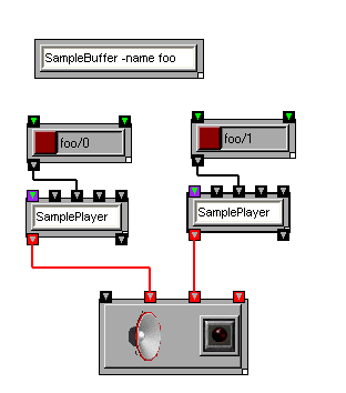
SamplePlayers stream audio from tables. You can easily start and stop streaming, define loop points, and vary the speed of streaming like on an old record or tape player. For more information and examples, visit the help patches for SamplePlayer and SampleBuffer, the looping tutorial and the chapter on time in OSW.
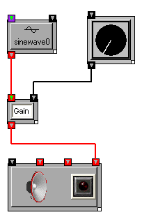
If you have tried out some of the oscillators or sample-playing functions in the previous section, you have no doubt learned the usefulness of scaling or amplifying your signals (especially scaling them down). After AudioOutput, the most important signal-processing transform in OSW is Gain transform, which allows you to scale a signal up or down a factor, much like a volume knob on audio hardware. Use it often!
Multiple signals can be mixed together using the Mixer transform.
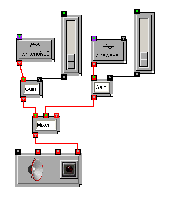
Note that Mixers only combine (i.e., add) signals. If you need fader controls to balance the signals, you can add Gain and slider transforms to inputs of the Mixer, as shown above.
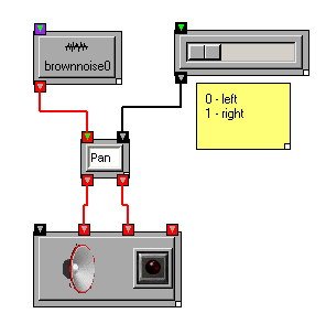
One common use of mixer-and-amplifier configurations is to pan mono signals among several channels. OSW provides two transforms for panning input signals to multiple outputs. Pan works much like a stereo panner a traditional mixer or hi-fi system, while PanHandler provides the ability to position a source in a multi-channel speaker configuration.
OSW includes a transform, Scope that displays audio signals in a traditional "oscilloscope"view.

You can use scopes to help visually debug signals, or test audio inputs prior to a performance, or otherwise help avoid embarassing situations. For more intense viewing and debugging of signals, you can dump the actual sample values to the console using the Print transform or to a text file using the TextOut transform.
We have so far covered the basics of how to get sound in and out of OSW, generate signals from simple synthesizers or audio files, scale them and move them around in various ways. However, this is really only the beginning. We now explore basic methods for modifying signals within OSW.
Among the basic building blocks are digital signal processing are delays, elements that shift signals backwards in time. Given a digital signal x(n) as defined above, the signal y(n) delayed by M samples can be described using the following equation:
y(n) = x(n-M)
In signal-processing diagrams, you will often see delay units labeled with z-M where M is the number of samples to delay the signal. Consider the following signal-flow containing such a delay element:

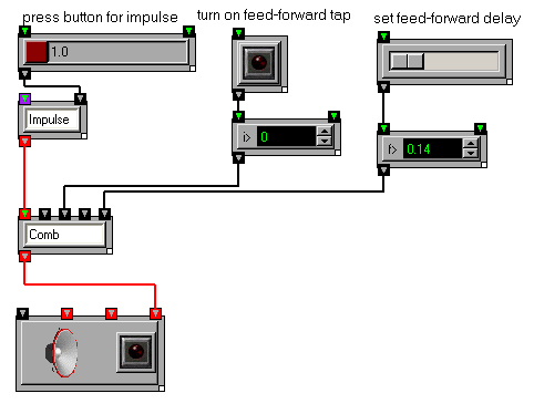
In this signal flow network, a signal is split into two identical copies, one of which is delayed. The two signals are then summed to create the feed-forward signal. Such a signal-flow network is called a feed-forward network, or feed-forward comb filter [Smith 2003]. An Impulse sent into this signal will be heard twice with a delay of M samples between the two impulses. You can experiment with the feed-forward comb filter tutorial patch in OSW. Note that OSW comb filters implemented using the Comb transform have one significant difference from the convention comb filter described above: the delay units are given in seconds rather than samples. This is an OSW convention that allows signal-processing elements to function independent of sample rate and use more intuitive controls.
If the tap is placed after the delay and the result is mixed with the original signal before the delay, a feed-back comb filter is created.

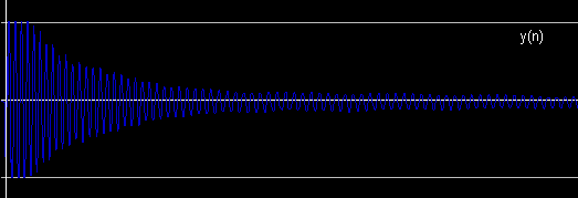
Without the amplifier in the feedback loop (indicated a triangle in the above diagram), the signal would loop back on itself forever. The amplifier is used to attenuate the signal and avoid infinite feedback. An impulse sent to such an attenuated feedback system would produce an output containing series of delaying impulses. Try experimenting with the feed-back comb filter tutorial patch. Change the duration of the delay. With short durations, the impulses are close together and you will perceive a single decaying tone, with longer durations, you will hear separate impulses, each one softer than its predecessor. A feed-back comb filter can be used to create echo or reverberation effects, as demonstrated by the echo machine tutorial. Flangers also make use of comb filters, but with variable delays.
The Comb transform used in the previous section is but one of a large class of signal-processing transforms called filters. Most filters can be described using a signal-processing network with delays and amplifiers, or using equations with delay and scaling variables. Below are the equation and signal diagram for a common filter called a biquad filter:

The biquad filter contains two feed-forward and two feed-back sub-filters with one-sample delays. The delay durations are fixed, but there are five variables for the amplifier elements, also known as filter coefficients. You can experiment with the coefficients of a biquad filter directly using the Biquad transform in OSW. However, you will likely find that its coefficients are less than intuitive. OSW provides several variations on the biquad filter that have more intuitive frequency-based controls. To understand frequency controls, recall that sounds are composed of many frequency components, indeed research has shown that this is essentially how the human ear perceives sound [Helmholtz 1875]. Thus, a waveform y(n) has a corresponding frequency-domain representation Y(ω), where ω is a "sample" of the frequency spectrum of a sound:
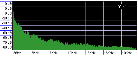
Frequency-domain representations will be described in greater detail in later chapters, for now the important concept to understand is that sections of the frequency-domain representation can be amplified or attenuiated. Think of the sliders on a graphic equalizer in a stereo system; raising or lowering the an equalizer fader amplifies or attenuates the sound in a particular range of frequencies.
The simplest filters that use frequency controls are Hipass and Lowpass, both of which take a single parameter called a cutoff frequency. In Hipass, frequencies below the cutoff are attenuated while frequencies above the cutoff are maintained. In Lowpass, the opposite occurs, frequencies below the cutoff are preserved while frequencies above the cutoff are attenuated.


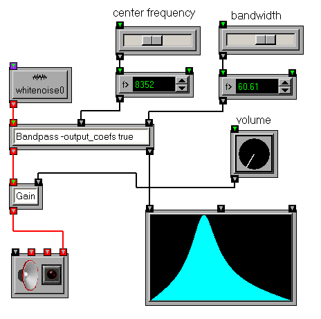
Another filter kind of filter, called a resonant filter, has two parameters, a center frequency and bandwidth. The center frequency works similar to the cutoff frequencies in hi-pass and low-pass filters, amplifying frequencies around the center frequency and attenuating frequencies farther away (both lower and higher). The bandwidth parameter defines the area around the center frequency that will be amplified. A narrow (low-valued) bandwidth means more amplification around the center frequency and more atenuation for other frequencies, while a larger bandwidth means more frequencies are preserved but less amplification (or "peaking") around the center frequency.

OSW includes two transforms Bandpass and TwoPoleResonz that implements a single resonant filter. Individual resonant filters or chains in series can be placed after frequency-rich sound sources, such as Phasors, noise oscillators or sampled sounds to change the timbre of the source sounds. This is a commonly-used sound-synthesis technique called subtractive synthesis. Resonant filters can also be grouped together into a parallel bank to produce complex and interesting sounds through another synthesis technique called resonance modeling. The Resonators transform implements an arbitrarily large bank of parallel filters to use in resonance modeling. Both subtractive synthesis and resonance modeling will be described in greater detail in the chapter on advanced sound synthesis.
It is interesting to note that Lowpass, Hipass, Bandpass and TwoPoleResonz are all implemented as special cases of Biquad; they convert the frequency-based controls to biquad coefficients.
As noted above, frequency response is important in understanding the behavior of filters. Some filters, such as low-pass filters, have relatively simple and intuitive frequency responses, while others are more complex. In fact, it is often difficult to predict the frequency response of a biquad filter from inspection of coefficients. Open Sound World includes a transform FrequencyResponse that can be used to explore the frequency response of filters. It takes a list of biquad coefficients and produces a frequency-amplitude plot of the response. In addition to raw biquads, several filter transforms, including Bandpass and TwoPoleResonz output coefficients that can be used by FrequencyResponse.
We have seen how several different kinds of filters respond to frequencies. So what about the comb filters explored in the previous sections? We present a special case of a comb filter, called an allpass filter that has a very interesting frequency response. A simple allpass filter can be constructed from a pair feedforward and feedback comb flters in which the delays are equal and the feedforward and feedback gains are mirror images (i.e., negations) of each other:

The Allpass transform implements a simple allpass filter using the topology illustrated above. The idea of a filter with a flat frequency response may not sound very interesting at first. However, allpass filters are very useful in applications where one wants to modify the temporal quality of a sound without changing the "color" or timbral quality of the sound. Reverberation is one such application, and allpass filters are often found in reverb algorithms.
Another property of allpass filters is that while the frequency response may be flat, the phase response is not. This property makes allpass filters useful building blocks for phase-shifter (or "phaser") effects.
You can record signals to audio files using the SampleWriter transform. It supports all the audio formats used by SampleBuffer and SampleStreamer, and can write multiple channels.
Unless otherwise indicated, all of the arithemetic operators and math functions work with signals. The same operation that is applied to numeric values is applied to each sample of an signal incoming signal. Some functions, of course, work better than others. Some common uses of arithmetic and math functions for signals include:
The user is encouraged to experiment with these and other functions to create interesting signals. However, beware of singularities (e.g., divisions by zero and certain values of functions like Tan, Sec, Csc, etc.) that may lead to excessive clipping and unstable behavior. Turn down the volume before experimenting with non-linear signal processing. Your ears will thank you for it.